Time Clock with Arduino Nano Circuit Diagram In conclusion, the Arduino Real Time Clock with Alarm System project, which makes use of the RTC DS3231 module, offers a thorough and approachable introduction to embedded systems. The methodically laid out stages, from Proteus simulation to code overview, make it easier to integrate the various parts for accurate timekeeping and alert features.
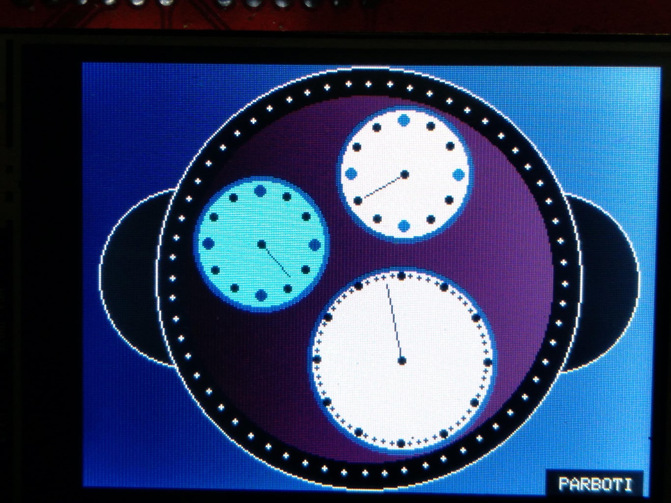
Introduction:- In this post I am going to make "Real time Clock " using 3.5 inch TFT touch LCD, Arduino Mega 2560 and DS3231 RTC module….Before starting…check the video from my YouTube channel.. Note:- If you are using Arduino You have to modify sketch. Because this sketch uses >100% of arduino UNO's memory
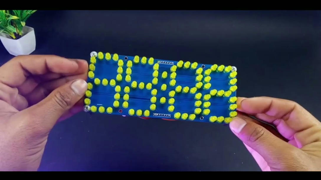
Alarms with Real Circuit Diagram
Now that we have seen a little bit about the Real Time Clock IC DS1307, we will proceed with the interface of Arduino and Real Time Clock. As mentioned earlier, the DS1307 RTC Module uses I2C Communication. In the Arduino Real Time Clock I2C interface, the Arduino Microcontroller always acts as Master and the DS1307 acts as Slave.

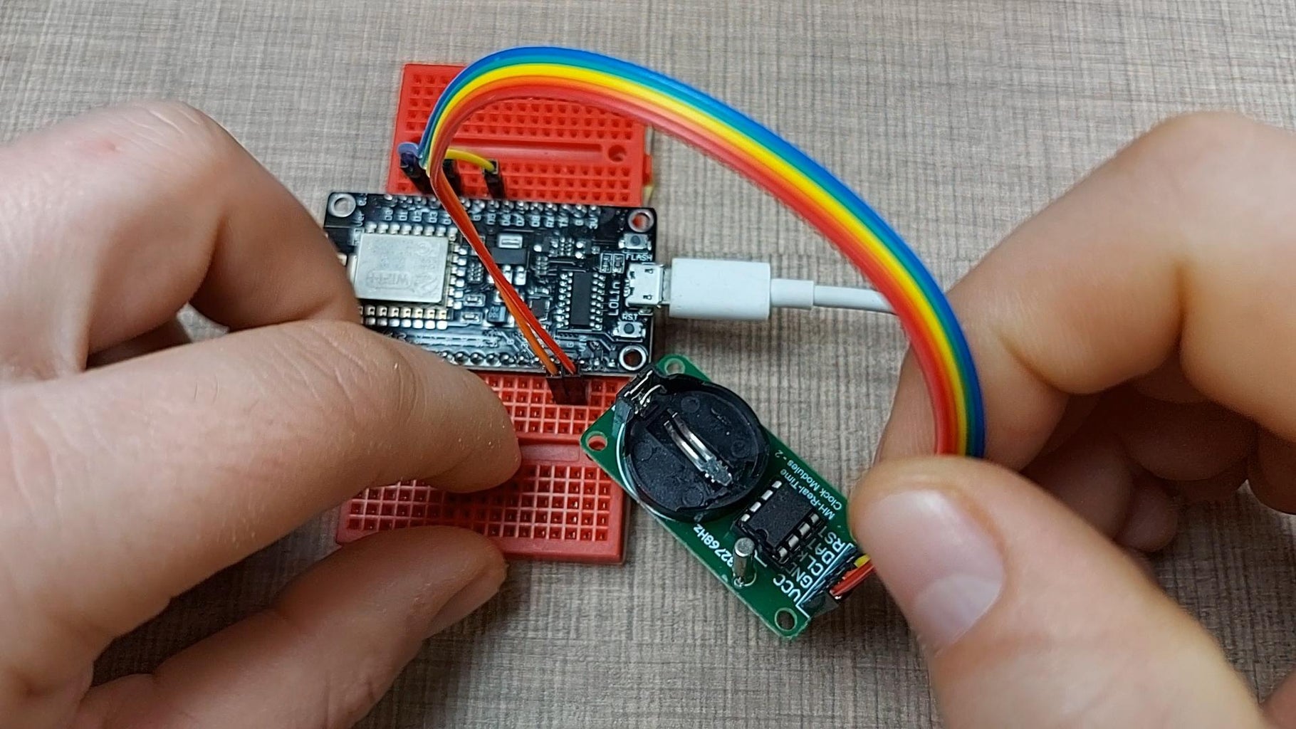
Learn how to use a DS3231 Real-Time Clock for accurate time and date in your projects! 50595 views • 3 respects. embedded. clocks. monitoring. Components and supplies. 1. Arduino UNO. Apps and platforms. 1. Arduino IDE. Project description. Comments. Only logged in users can leave comments. login. Once we connect the module we need to program the Arduino Board to work with the Real Time Clock. However, when it comes to programing a communication between Arduino and an I2C module the code isn't that small and easy. Luckily, there are already several libraries for the DS3231 RTC which can be found on the internet.

Real Time Clock With Alarm Using Arduino And RTC DS3231 Circuit Diagram
The DS3231 real time clock module keeps track of the time even when the module is not powered. It has a built-in 3V battery, which keeps updating the time. We will get the time and date from the RTC module using the library functions and then we will compare this time with the alarm time that we have set in the code. A Real-Time-Clock is especially useful when you want to let the Arduino sleep for longer periods of time. The maximum sleep duration for an Arduino Uno is 8 seconds. But with an RTC you can have arbitrary long sleep durations, which great to extend the battery life of data loggers, for instance.
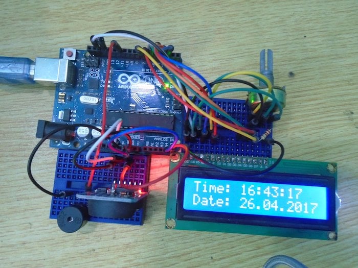
Learn how to display the current date and time on an LCD screen an external real-time clock (RTC) module with Arduino.0:00 introduction0:41 module close-up2:

Arduino Real Time Clock Tutorial using DS1307 Circuit Diagram
To install the library: Open the Arduino IDE and go to Sketch > Include Library > Add .ZIP Library.Search for the downloaded library and click OK. Arduino Code for DS1307 RTC Module Here's a basic example code to get you started with the DS1307 RTC module.